The balance bar setup is a bit odd. Basically it is a Tilton balance bar, but the sleeve that you'd expect in the pack isn't there. Instead, it is already welded into the brake pedal by Hawk's fabricator.
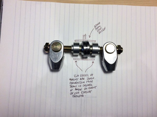
An addition to the kit is a pair of aluminium 'movement restrictors' that Gerry supplies. These aren't covered by the Tilton guide or the Hawk build manual. They are included so that if a circuit fails, the balance bar is restricted to 10 degrees of movement, enabling the other circuit to carry on doing some braking.
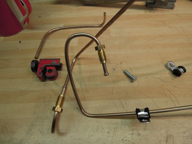
Here's what you get in the kit, plus some drawings to illustrate how it works:
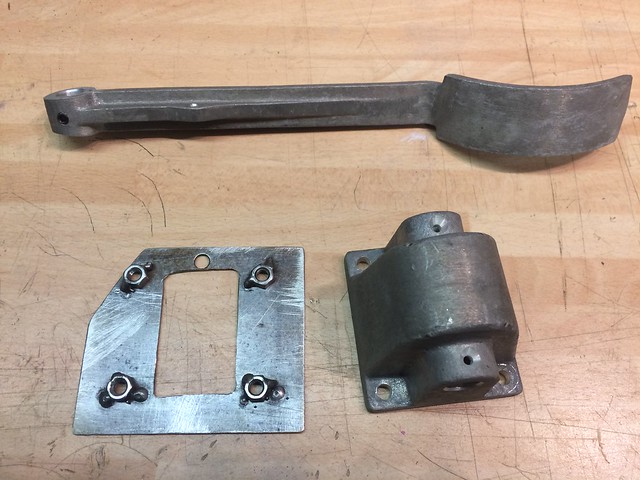
Here's a dismantled shot - the 'thingy' in the diagram is the Hawk-supplied movement restrictor:
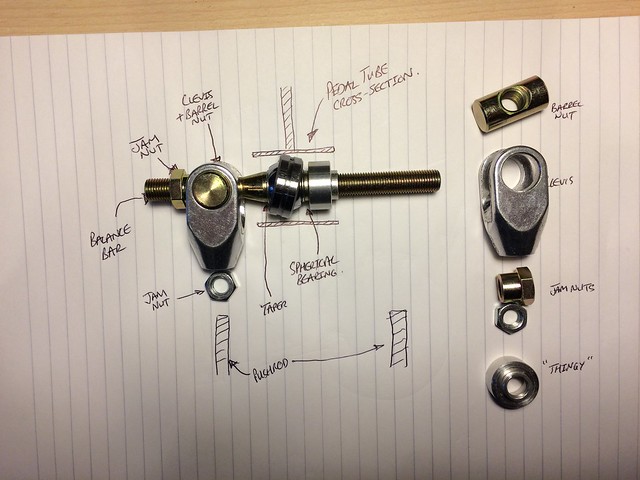
These movement restrictors are wound right up to the tapers either side of the central spherical bearing and loctited in place.
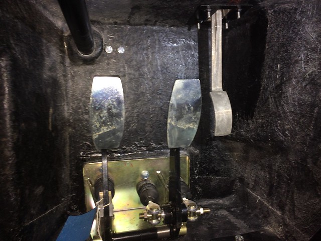
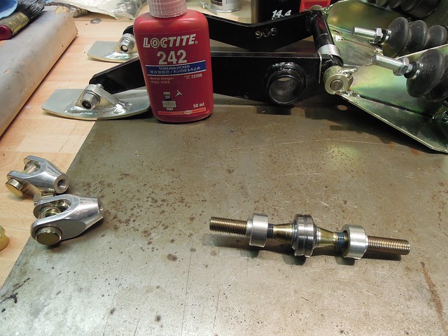
Since the sleeve and brake pedal isn't exactly centred between the two brake master cylinders, I had to do a bit of thinking on the assembly. Here's what I did:
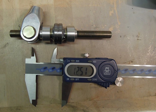
1. Put the movement restrictors on, and loctite in place. (They are yet to be wound up to the taper in this photo):
2. Put bar into sleeve in pedal to make sure it fits - I had to remove some powdercoat.
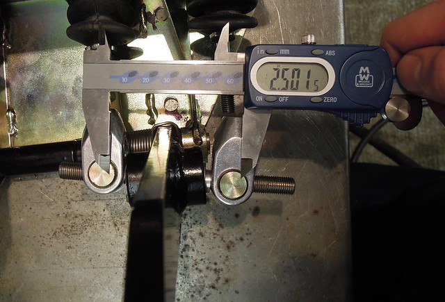
3. Measure centres of two cylinders:

4. Halve that figure and wind one barrel nut/clevis onto the balance bar.
5. Put the balance bar into the sleeve. Wind the first master cylinder into the clevis. It must go in at least 6 threads. I did this by rotating the entire master cylinder, since the clevis could not be rotated (obviously).
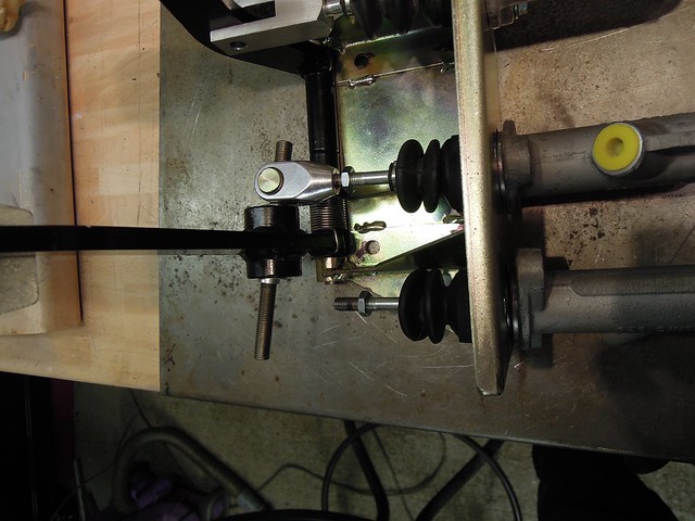
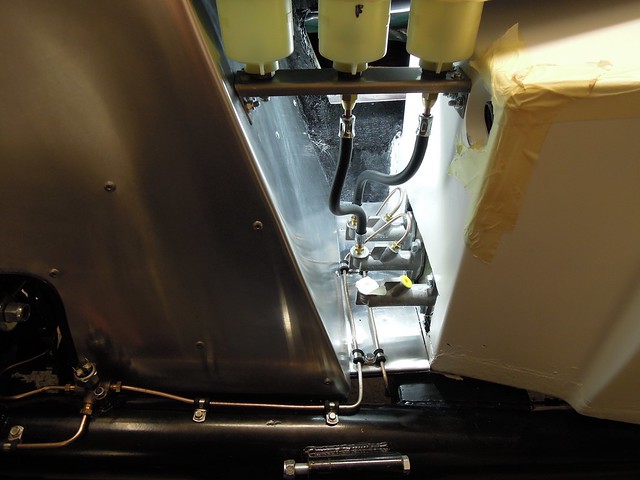
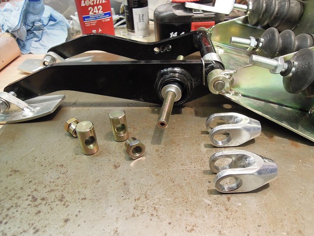
6. Put the other barrel nut/clevis on the other end. Make sure the centres of the two barrel nuts are the same spacing as the centres of the master cylinders:
7. Attach the second master cylinder to its clevis:

The Tilton instructions talk about adjustment from this point on, but that can only be done once the brake system has fluid in it - I wasn't at that stage, so I'll do that later.
Andy