The cut off piece of arch was then placed onto a sheet of steel & a line scribed around it. This was then cut out with an air shears. The bottom edge of the arch was then drawn onto the sheet for the second cut
The arch was then cut out
The edge of the arch where it had been cut was then trimmed to get it smooth
The new arch was then taped into place to check it fitted ok
This is how it looks from the front.
The new arch will be taped to the body with duct tape & the inside will then be gel coated & have the fibreglass matt layed up on the inside, which is the same process that I'm going to do with the front valance. Once it's all cured I can remove this panel and sand the gel coat to form a radius to the edge of the arch. I'll add a bit of a taper to the arch "face" at the bottom edges, but will wait until it has some tyres on before doing that. On the aluminium shell this will have a wired edge. I still need to finish off the bottom of the arch where it meets the valance & sill, but it's not a lot of work to do that & I'll probably do it when I get to the fibreglassing stage. All I need to do now is to use this piece as a template for the other side & repeat the process
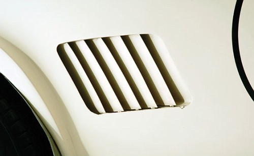
Here's one for you Nik , I had another 5 minutes or so free whilst waiting for more primer to flash off, so thought I'd cut out the side vent. The vents on 39PH & 644CGT are much bigger than the originals and I liked the look so thought I'd go with it. Again in my haste to get it done, I didn't photograph how I did it . I measured out the size of the apperture to be cut & used a hole saw in the corners to cut out the radii. I then used a cutting disc to remove the 'glass between the holes.
When I get a spare few minutes I'll make up the flange of the inner surround for it so that it can be glassed into place
What do you mean by " flange of the inner surround "? There isn't a flange on the side vent cutouts. The aluminium was simply folded back on itself to create a double thickness to the edge. The upper and lower edge returns have extensions that fold at 90 degrees to create tabs that the vents fasten to. That probably doesn't make much sense, so I'll try to find a picture to help explain.
PaulB wrote:Looking really good Nige, keep them coming.
What do you mean by " flange of the inner surround "? There isn't a flange on the side vent cutouts. The aluminium was simply folded back on itself to create a double thickness to the edge. The upper and lower edge returns have extensions that fold at 90 degrees to create tabs that the vents fasten to. That probably doesn't make much sense, so I'll try to find a picture to help explain.
Paul
Hi Paul, I probably didn't explain that too well did I?. What I was trying to say is that I'll make a 90deg lip on the apperture I've cut out (where the "grilles" fit) I used the word "flange", probably wrongly, to describe the 90 deg piece, Does that make better sense?
As Paul says, the 90° flanges are only a couple of inches long in the top and bottom surfaces and have holes in them to mount the grilles.
The rest of the return, most of it, is 180° pressed flat. No wired edge on these.
Roger King wrote:As Paul says, the 90° flanges are only a couple of inches long in the top and bottom surfaces and have holes in them to mount the grilles.
The rest of the return, most of it, is 180° pressed flat. No wired edge on these.
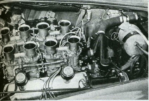
Thanks Roger/Paul, that's appreciated, do you have a close up from the engine bay side showing how the grilles are fitted for referance? In this picture I took of of Rob Bremners 289, the 90 deg flange appears to run around the perimeter of the apperture, is this correct?
Anyone know how they were fitted to 39PH or 644CGT? there are just soooo many discrepancies on these cars aren't there?
Migge wrote:COB 6041 had a fatal front crash at SPA 6h in 2007. I picked up 2 pieces of body filler from the front. The whole front was shaped from filler up to 1 1/2"!
The top photo in my post above is after that crash, you can see the thickness of filler on the driver`s side wing, and on the other side, you can see that it was wrapped in duct tape after an earlier incident! Ouch!
agnoraan wrote:Here's one for you Nik , I thought I'd cut out the side vent. The vents on 39PH & 644CGT are much bigger than the originals...
Blimey... without the slats in they look HUGE!
I`ve trawled my archives but have no inside photos of the vents, like this one:
No photos handy at the mo, I'll have a look tomorrow. What you are seeing is the slats themselves. They were made with a wide frame around them, each slat rivetted into the frame. The frame was then held to the body by two screws, one at the top and one at the bottom, which threaded into the aforementioned small 90° returns.
Looks like there was an additional bracket (due to these being taller than standard?) visible in the 39PH enginebay shot, just above the rocker breather.


, I thought I'd cut out the side vent. The vents on 39PH & 644CGT are much bigger than the originals...